During the early years of the space age techniques were developed to track objects in orbit and predict their future position. The mathematical technique for calculating an orbit is called a Simplified General Perturbations (SGP) model. These models were first used in the 1960s and were refined during the 1970s. This work was done by NORAD – the North American Aerospace Defense Command.
“Satellite watchers in the Space Computational Center, NORAD Headquarters, track all the satellites orbiting earth.” Credit: U.S. Information Agency / National Archives, 1982
The computations were performed on large mainframe computer systems that cost several million dollars each. One of these computers was used for ballistic missile warning. A second was dedicated to space surveillance and tracking satellites. A third was available on standby as a backup system in case one of the primary computers failed. The various objects being tracked in air and space were displayed on consoles such as the one shown above.
The invention of magnetic bubble memory was once seen as a
revolutionary computer development – the wave of the future. It is now a
nearly forgotten technology.
“Many
persons expect that the most dramatic changes in digital systems will
result from magnetic-bubble chips that could well hold a million or more
bits in the not-too-distant future. Along with charge-coupled devices,
these memories show promise of replacing magnetic tape and disks for small systems.” [emphasis in the original]
– Understanding Digital Electronics, Texas Instruments, 1978
One
of the more unusual computer objects that I’ve collected over the
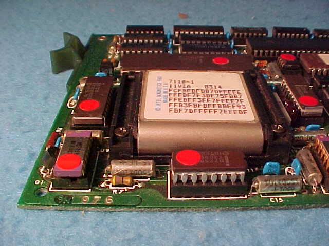
years uses this memory. It is called the QSB-11A Bubbl-Board. I was told
by the person that sold it to me that it had been used in a system at
Los Alamos National Laboratory. I have no idea how it was used. Given
the nuclear research conducted there I sometimes wonder if I should
check to see if it is “hot.”
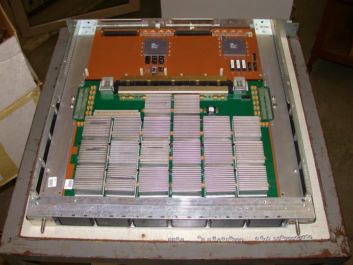
The J90 logic is implemented using application-specific integrated circuit (ASIC) chips fabricated by IBM. There are 10 unique ASICs that are found in the processor and memory modules. A typical J90 system could contain about 230 of these CMOS chips. The photo below shows a processor module with the cover removed. Each module contains 4 scalar/vector processors. The space at the top of the board can be used for optional HIPPI interfaces or Y1 Channels to additional I/O Processors.
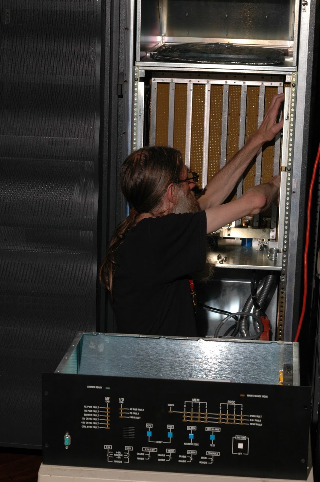
The Cray J916 was featured at our monthly open house this past Saturday. We spent most of the day talking to visitors about the system and showing them the rest of our collection. We did make some progress in the morning before we opened. Dave took some photos while I was working.
Working on the system clock board on the J90 backplane.
The Central Control Unit is in the foreground.
Everything seems to be functional with one exception – there is a system clock PWR FAULT light showing on the Central Control Unit. We suspected a loose cable or board connector and traced the signal paths. We couldn’t find the cause of the fault and will need to dig deeper another time.
How does the performance of a 20 year old supercomputer compare to the devices that we use today? Let’s compare the Cray J916 to a recent laptop and a smart phone.
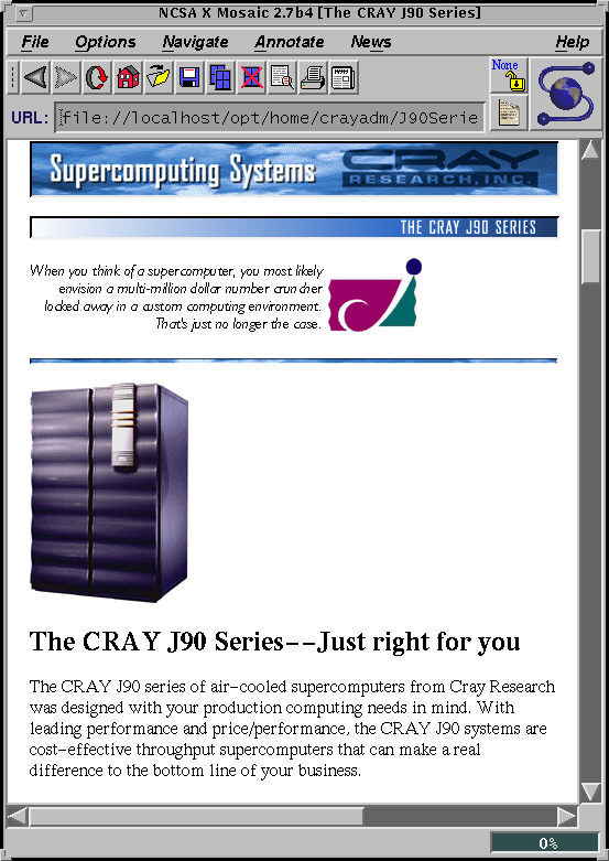
According to an archived copy of the Cray J90 Series webpage the vector processors have a theoretical peak performance of 200 mflops each, giving our 8 CPU system 1.6 gflops. But, your mileage may vary depending on the code that is running. One of the standard benchmarks used for supercomputers is LINPACK. Results for a J916 with the same configuration as ours are listed in Performance of Various Computers Using Standard Linear Equations Softwareby Jack J. Dongarra from June 1995. An 8 CPU system was measured at 1.436 gflops, an efficiency of about 90% of the theoretical peak.
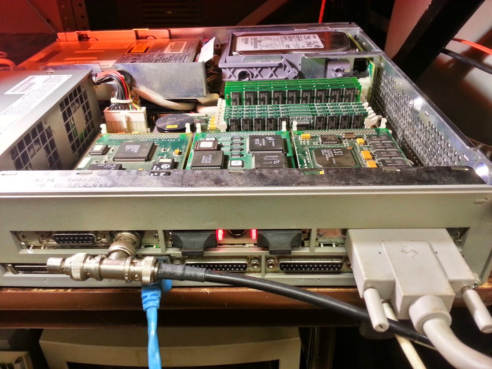
We are at the point where we can power up the Cray and begin configuring it. Next we need to work on the J90 System Console (or SWS, the Service WorkStation.) This is used to net boot the I/O Processors in the I/O Subsystem, which in turn loads UNICOS into the J90 main memory. The SWS is a Sun SPARCstation 5 running Solaris. We didn’t get the original SS5 that came with the Cray so we had to build one.
The SWS with ThinWire Ethernet, FDDI, and graphics.
We had a couple of these lying around, but they weren’t in very good shape. We cobbled together a system from the parts which is better configured than what would have been used when the J90 was installed in 1996. This system has the maximum of 256 MB of RAM and a 24 bit S24 TCX graphics card.
There are two Ethernet interfaces. The one on the SBus card is 10BASE2, more informally known as ThinWire. This is only used to connect the SWS to the two I/O Processors in the I/O Subsystem. This allows the IOPs to net boot from the SWS and is also used to configure and manage the system.
In a previous post I described the power requirements of the Cray J916 and the importance of the Central Control Unit (CCU) monitoring for faults. This is rather critical as the machine won’t function properly unless these hardware status signals check out.
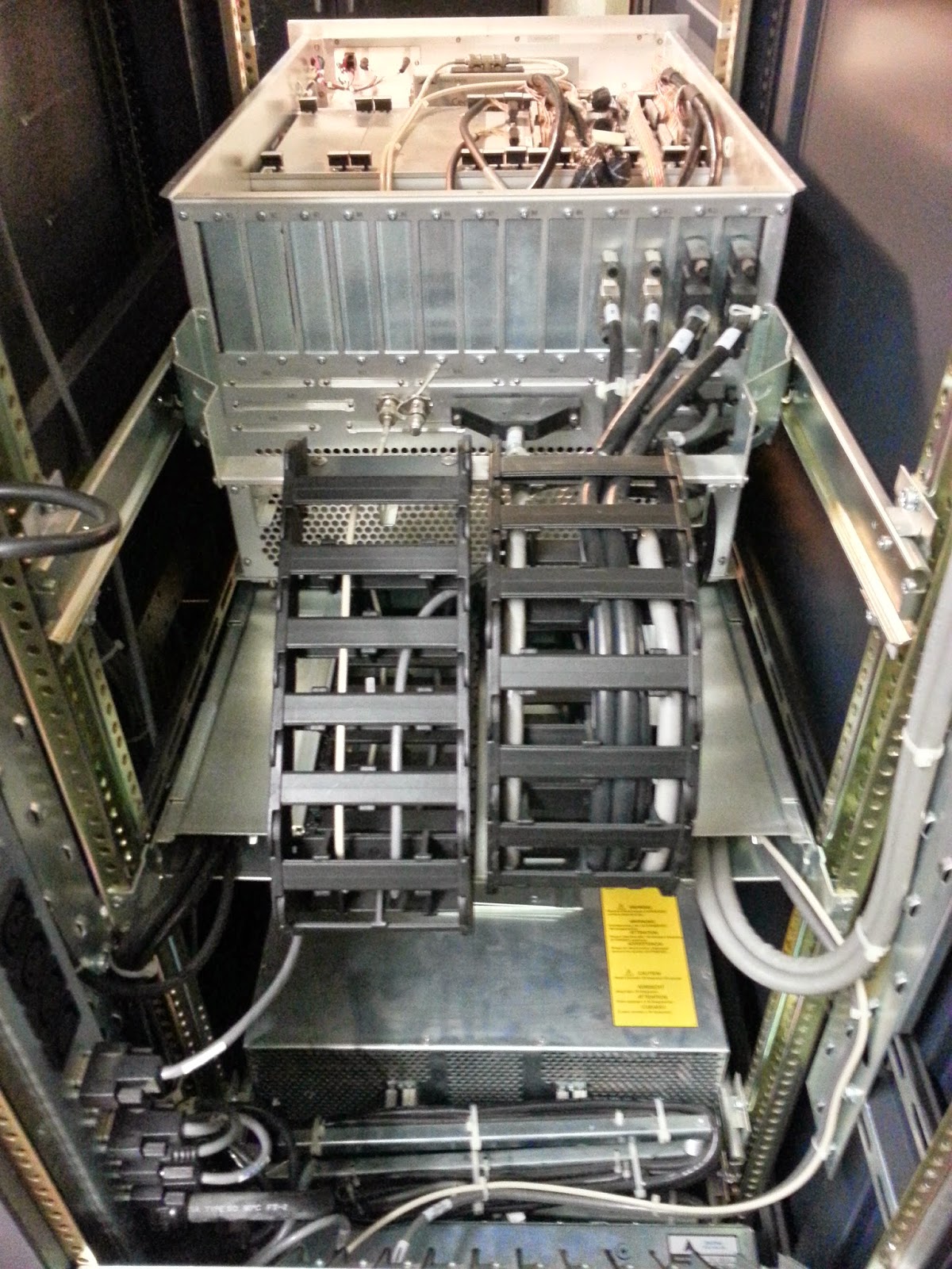
The back of the I/O Subsystem in the Peripheral Cabinet. This is the cleanest cable management system I’ve ever seen, but tracing cable paths while re-wiring the system was time consuming.
With the system re-cabled we can power it up and begin testing the hardware. We noticed that the CCU contains rechargeable D size batteries. Yes, we received a donated Cray and batteries were included! They were, of course, very dead. The system had been unplugged for a long time.
The Retro-Computing Society of RI will be featuring the Cray Jedi at the next open house on Saturday July 19th at our facility in Providence. This fall is our 20th anniversary. (If you are looking for gift ideas we prefer the modern platinum to the more traditional china.)
A short time after our group formed we made arrangements for a private tour of The Computer Museum in Boston. Our member Carl has a detailed write-up of the visit and the collection that we saw. Not long after our 1996 visit TCM closed and the collection was moved to a new home on the west coast which became the Computer History Museum.
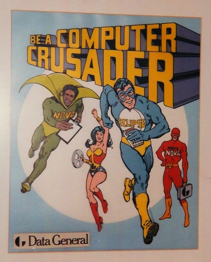
A Data General poster depicting the Nova and Eclipse minicomputers as superheros.
From the collection of the Computer History Museum.
Another of our members created The Retro-Computing Lab Millspace Tour which gives a nice snapshot of what we were doing between late 1996 when we moved into the Eagle Street facility and mid-1998 when the page was last updated. Warning:
This page may take some time to load if you are viewing graphics.
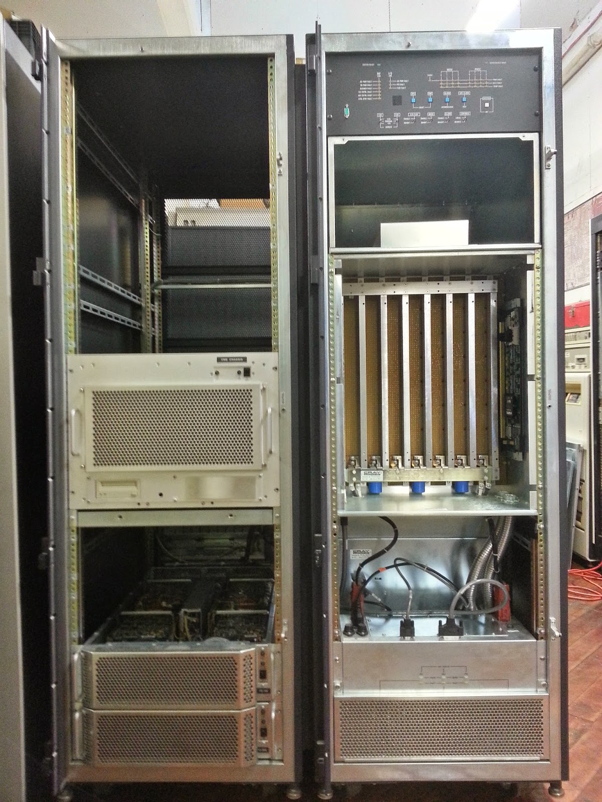
What’s inside a Cray J90? I’m going to take a pause in the restoration to “pop the hood” and describe what’s under the covers. Here we have the two cabinets bolted together with the doors and most of the panels removed. On the right is the Processing Cabinet and on the left is the Peripheral Cabinet.
The Cray J916 with the front doors and many of the filler panels removed.
The Processing Cabinet has a Central Control Unit at the top which has LEDs that display status and fault conditions. Below that is a plenum space for the cooling blower intake and dust filters. Next is the backplane (the Processor and Memory Modules are inserted from the back.) Under that is the blower which exhausts out the back. At the bottom are the 48 volt DC power supplies.
The Peripheral Cabinet is moderately configured with plenty of space for expansion. In the center is the I/O Subsystem VME Chassis which contains two VME backplanes. Each contains a SPARC single-board computer which functions as an I/O Processor (IOP.) The remaining VME slots contain the system interfaces including Ethernet, disk controllers, and the I/O Buffer Boards (IOBB) that transfer data from peripherals to the J90 processors and memory. At the bottom are two disk arrays.
The Retro-Computing Society of RI is located in the Atlantic Mills in the Olneyville neighborhood of Providence. We have a 1,500 sq. ft. facility in a mixed-use complex that was originally a worsted mill during the industrial revolution. It suits our needs quite well with amenities like a loading dock and a freight elevator. As I described in the previous installment, the system weighs more than a half ton. It was surprisingly easy to move as it has well designed casters that allow it to be smoothly rolled around. Now that it has arrived we need a plan to plug it in. Our electrical panel was a bit under-powered for running the Cray.
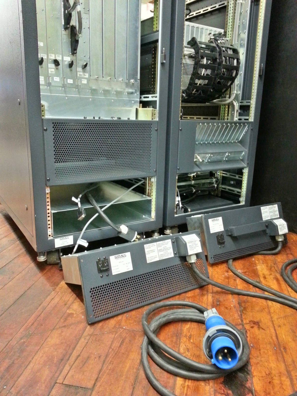
The back of the J916 with the two cabinets bolted together. Each cabinet has an AC power entry box which we had removed to prevent damage to the power cord during the move.
The system requires three-wire, single-phase, at 240 volts. A fully configured Processor Cabinet could draw a maximum of 4,200 watts while a full Peripheral Cabinet could draw up to of 3,600 watts. Our J916 is a moderately configured system which is about one half full. There is plenty of space for expansion to add additional drive bays, for example. There is a helpful Electrical Requirements Worksheet in the Preparing for a System Installation manual. For this configuration we calculate that both cabinets draw a total of about 2,000 watts or so. The property manager scheduled an electrician to upgrade our service and install the receptacles. We also made other changes to make it easier to power up some of our other machines that we haven’t been able to run recently. The work was completed on June 30, 2014. Continue reading Kilowatts, Control Cables, and Cooling→