Tag Archives: Retro-Supercomputing

Power Up

The Cray J916 was featured at our monthly open house this past Saturday. We spent most of the day talking to visitors about the system and showing them the rest of our collection. We did make some progress in the morning before we opened. Dave took some photos while I was working.

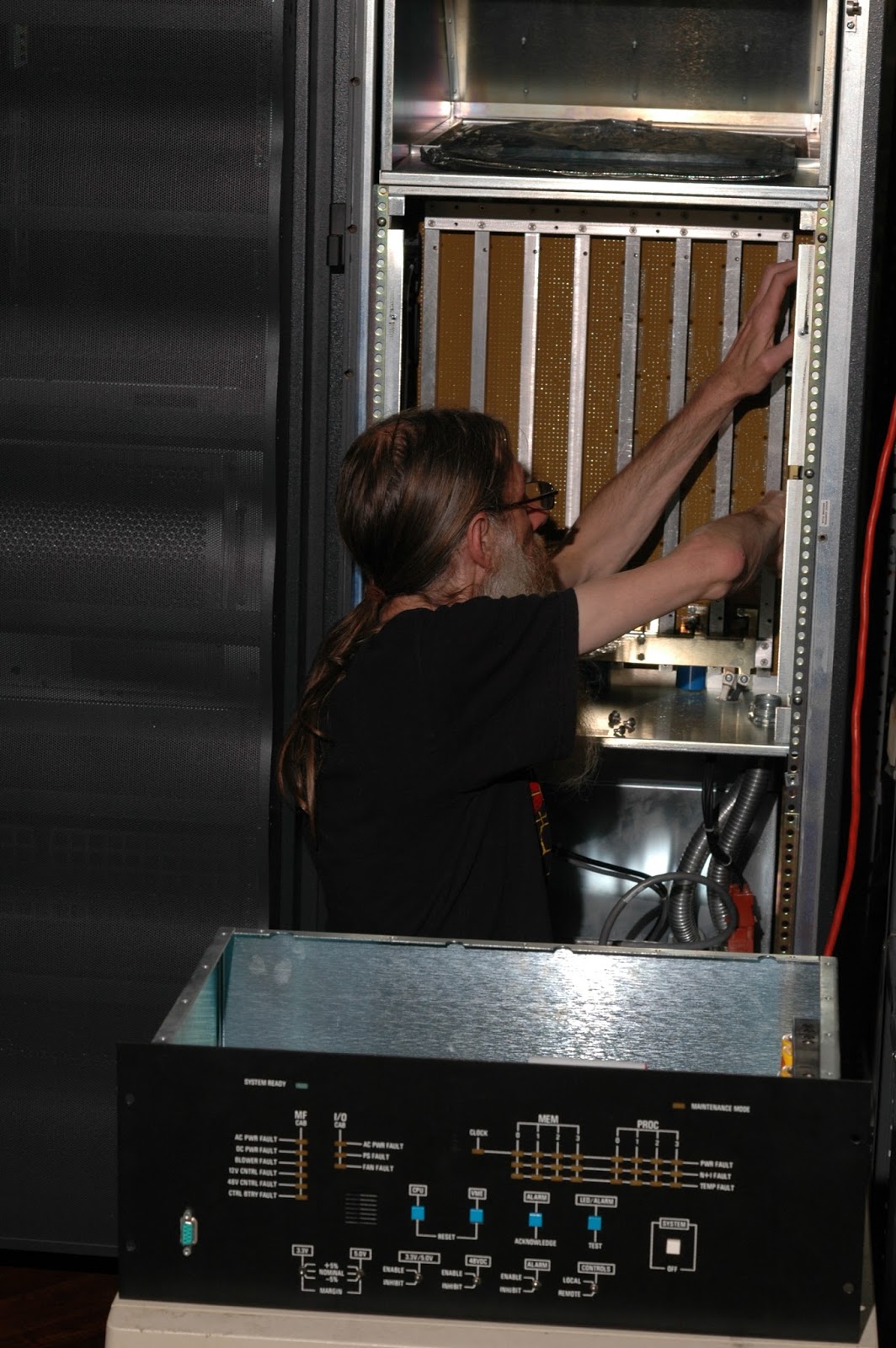
Working on the Cray J90 backplane
Working on the system clock board on the J90 backplane.
The Central Control Unit is in the foreground.

Everything seems to be functional with one exception – there is a system clock PWR FAULT light showing on the Central Control Unit. We suspected a loose cable or board connector and traced the signal paths. We couldn’t find the cause of the fault and will need to dig deeper another time.

Continue reading Power Up →

bootp

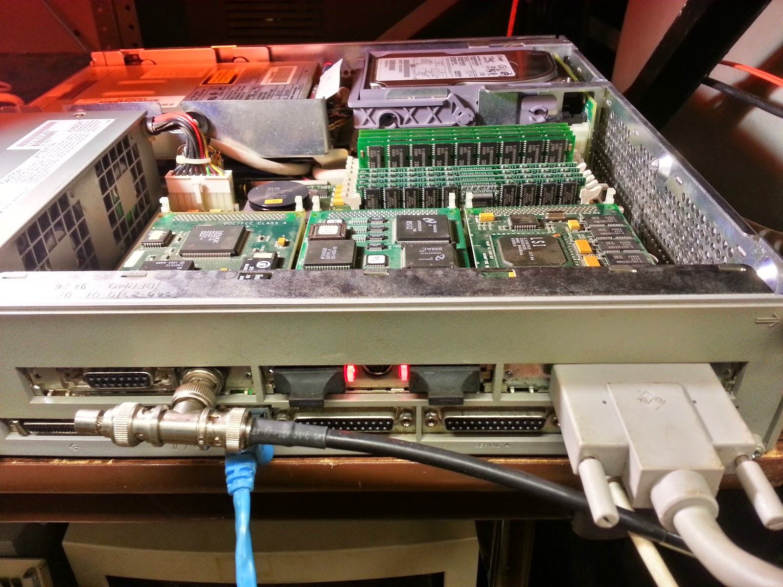
We are at the point where we can power up the Cray and begin configuring it. Next we need to work on the J90 System Console (or SWS, the Service WorkStation.) This is used to net boot the I/O Processors in the I/O Subsystem, which in turn loads UNICOS into the J90 main memory. The SWS is a Sun SPARCstation 5 running Solaris. We didn’t get the original SS5 that came with the Cray so we had to build one.

Sun SPARCstation 5
The SWS with ThinWire Ethernet, FDDI, and graphics.

We had a couple of these lying around, but they weren’t in very good shape. We cobbled together a system from the parts which is better configured than what would have been used when the J90 was installed in 1996. This system has the maximum of 256 MB of RAM and a 24 bit S24 TCX graphics card.

There are two Ethernet interfaces. The one on the SBus card is 10BASE2, more informally known as ThinWire. This is only used to connect the SWS to the two I/O Processors in the I/O Subsystem. This allows the IOPs to net boot from the SWS and is also used to configure and manage the system.

Continue reading bootp →

System Ready

In a previous post I described the power requirements of the Cray J916 and the importance of the Central Control Unit (CCU) monitoring for faults. This is rather critical as the machine won’t function properly unless these hardware status signals check out.

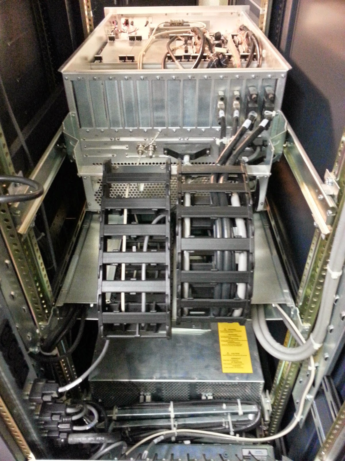
Back of the IOS and cabling
The back of the I/O Subsystem in the Peripheral Cabinet. This is the cleanest cable management system I’ve ever seen, but tracing cable paths while re-wiring the system was time consuming.

With the system re-cabled we can power it up and begin testing the hardware. We noticed that the CCU contains rechargeable D size batteries. Yes, we received a donated Cray and batteries were included! They were, of course, very dead. The system had been unplugged for a long time.

Continue reading System Ready →

Under the Covers

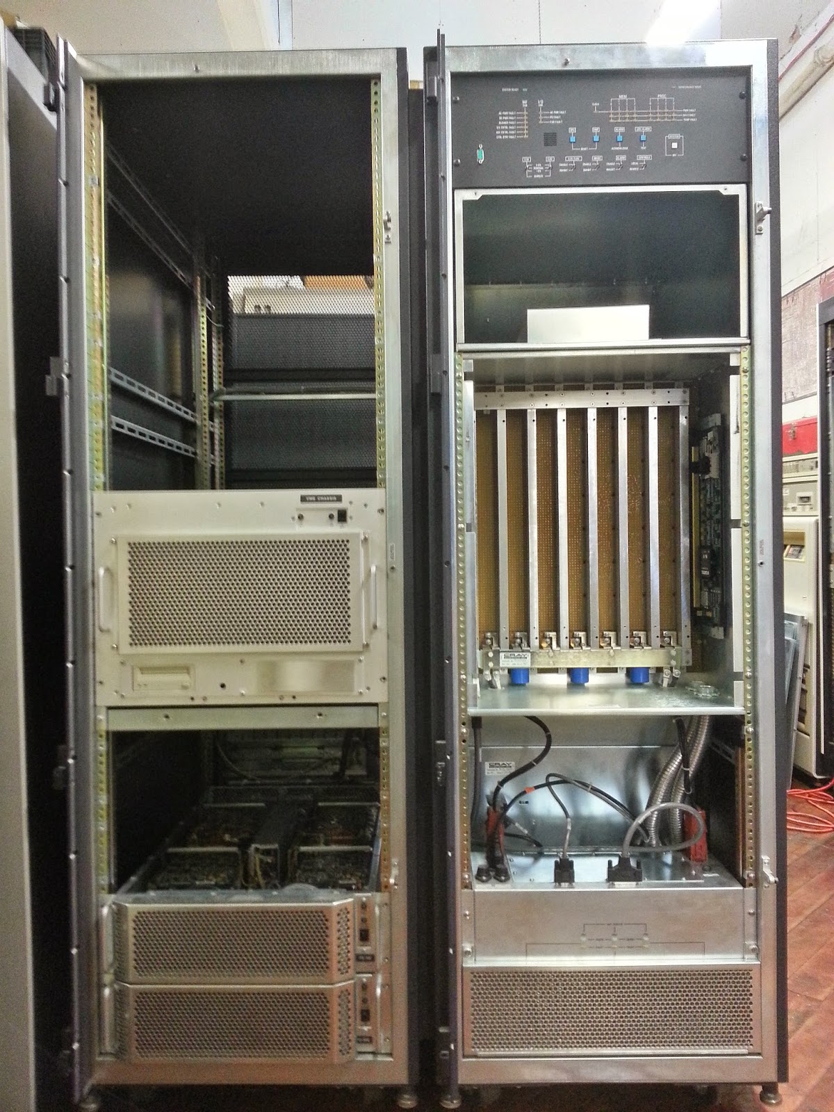
What’s inside a Cray J90? I’m going to take a pause in the restoration to “pop the hood” and describe what’s under the covers. Here we have the two cabinets bolted together with the doors and most of the panels removed. On the right is the Processing Cabinet and on the left is the Peripheral Cabinet.

Cray cabinets opened
The Cray J916 with the front doors and many of the filler panels removed.

The Processing Cabinet has a Central Control Unit at the top which has LEDs that display status and fault conditions. Below that is a plenum space for the cooling blower intake and dust filters. Next is the backplane (the Processor and Memory Modules are inserted from the back.) Under that is the blower which exhausts out the back. At the bottom are the 48 volt DC power supplies.

The Peripheral Cabinet is moderately configured with plenty of space for expansion. In the center is the I/O Subsystem VME Chassis which contains two VME backplanes. Each contains a SPARC single-board computer which functions as an I/O Processor (IOP.) The remaining VME slots contain the system interfaces including Ethernet, disk controllers, and the I/O Buffer Boards (IOBB) that transfer data from peripherals to the J90 processors and memory. At the bottom are two disk arrays.

Continue reading Under the Covers →

Kilowatts, Control Cables, and Cooling

The Retro-Computing Society of RI is located in the Atlantic Mills in the Olneyville neighborhood of Providence. We have a 1,500 sq. ft. facility in a mixed-use complex that was originally a worsted mill during the industrial revolution. It suits our needs quite well with amenities like a loading dock and a freight elevator. As I described in the previous installment, the system weighs more than a half ton. It was surprisingly easy to move as it has well designed casters that allow it to be smoothly rolled around. Now that it has arrived we need a plan to plug it in. Our electrical panel was a bit under-powered for running the Cray.

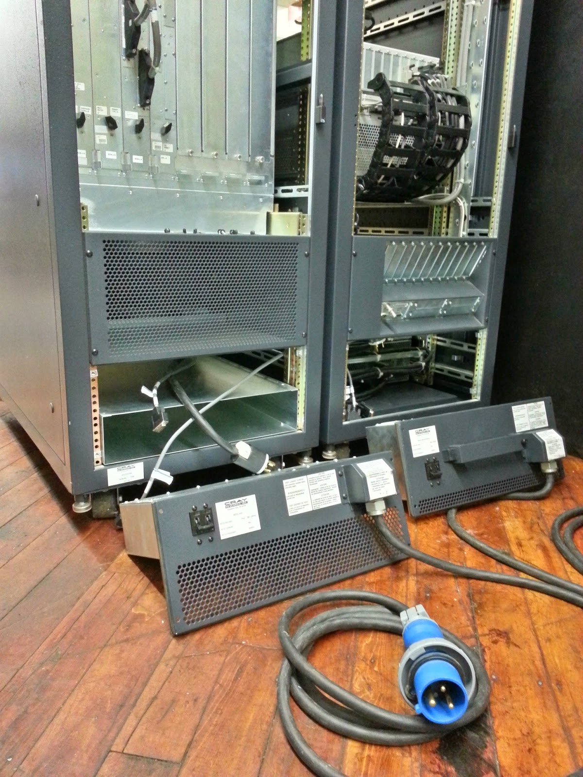
The back of the Cray
The back of the J916 with the two cabinets bolted together. Each cabinet has an AC power entry box which we had removed to prevent damage to the power cord during the move.

The system requires three-wire, single-phase, at 240 volts. A fully configured Processor Cabinet could draw a maximum of 4,200 watts while a full Peripheral Cabinet could draw up to of 3,600 watts. Our J916 is a moderately configured system which is about one half full. There is plenty of space for expansion to add additional drive bays, for example. There is a helpful Electrical Requirements Worksheet in the Preparing for a System Installation manual. For this configuration we calculate that both cabinets draw a total of about 2,000 watts or so. The property manager scheduled an electrician to upgrade our service and install the receptacles. We also made other changes to make it easier to power up some of our other machines that we haven’t been able to run recently. The work was completed on June 30, 2014. Continue reading Kilowatts, Control Cables, and Cooling →

Customer Name (if not confidential)

It was about four years ago when I first learned that there was still a Cray in the Department of Physics at Brown University. The machine was in the same building as my office; for years I had no idea it was sitting idle just a few floors above me. My colleague Prof. Ian Dell’Antonio facilitated the donation to the Retro-Computing Society of RI. He uses the high energy theory cluster for research on observational cosmology and gravitational lensing.

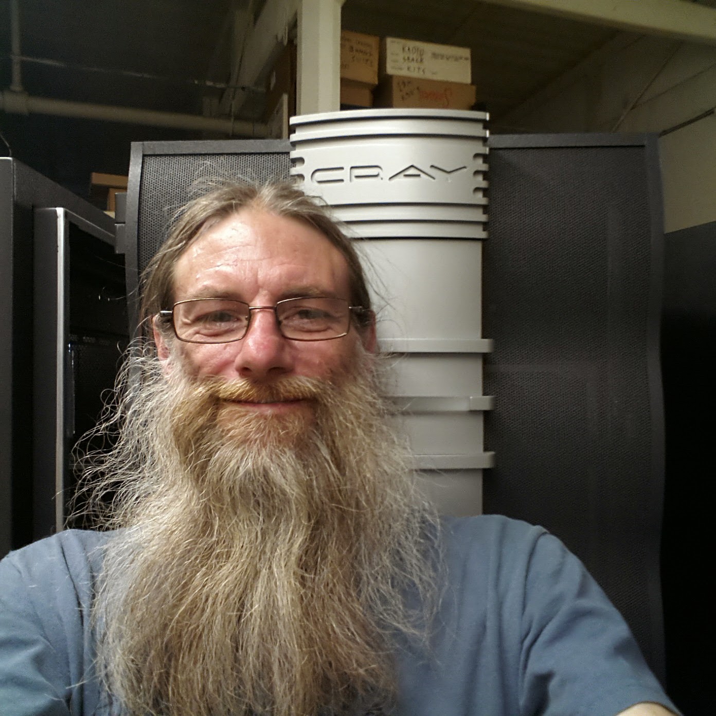
Selfie with the Cray
My other computer is a Cray…

In my previous installment I described the Theory Computing Cluster machine room where the Cray J916 had been used for high energy theoretical physics research at Brown University. It was installed in 1996. I’m not sure exactly when they stopped using it. I was told that it was difficult to program and had been unused for some time. Supercomputers tend to have a rather short shelf life.

We first moved the Cray to Brown’s Science Center where it was on display for a few years. Before it could be safely moved I had to “split” the cabinets. There is one Peripheral Cabinet housing the I/O Subsystem and disk arrays. The second cabinet is the mainframe, or Processing Cabinet, which contains the CPUs and memory. The Cray documentation sometimes uses the archaic definition of mainframe to refer to the primary frame (or cabinet) that contains the central processor. The Oxford English Dictionary cites a usage from Honeywell in 1964 and gives this definition:

mainframe, n.

2. Computing. Originally: the central processing unit and primary memory of a computer. Now usually: any large or general-purpose computer, esp. one supporting numerous peripherals or subordinate computers.

The two cabinet are bolted together when it is installed. There are a number of data and control cables between the two cabinets that I carefully disconnected. Then I removed the AC power entry box in each cabinet to prevent the power cord from getting damaged during the move. A fully configured Peripheral Cabinet could weigh as much as 800 lbs and the Processing Cabinet up to 1,000 lbs. This machine is moderately configured and we estimate that the entire systems weighs more than half a ton. Machines like this were often, and accurately, referred to as big iron.
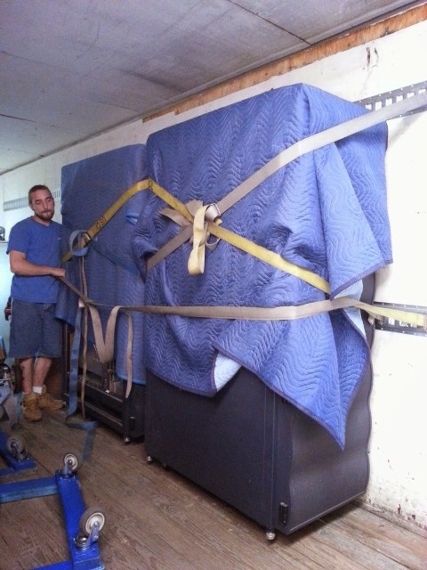
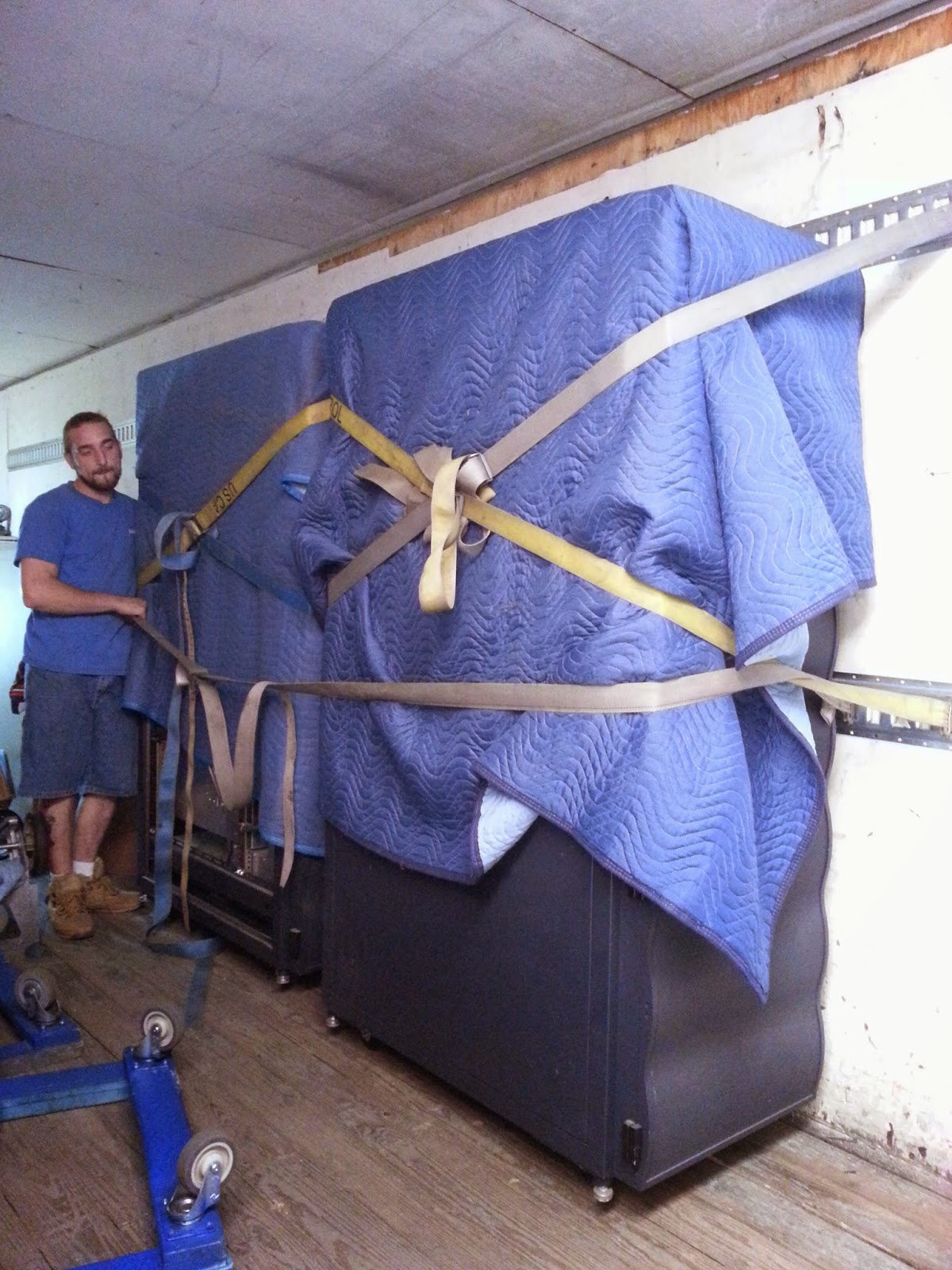
The Cray on a truck
Moving day. Our facility has a loading dock and freight elevator.

The Cray arrived at our facility on June 23, 2014. We then began to read the fine manuals:

  • Preparing for a Cray J916 System Installation
  • Hardware Installation Procedures – Cray J916
  • Automated Confidence Testing – Cray J90 Series

There was also a form called the Installation Report which the customer was expected to fill out to evaluate the delivery and installation of the system and then send the form back to Cray for quality control. The top of the form has a line that is labeled: Customer Name (if not confidential)

Before we could reassemble the system our next task was to come up with a plan on how we were going to plug it in…

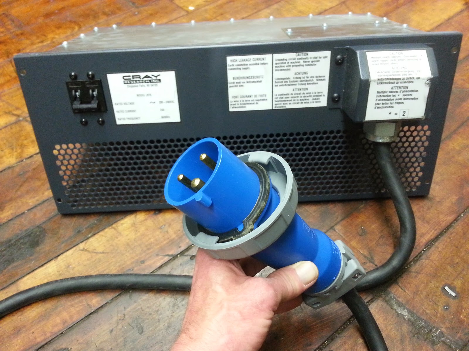
Power cord
One of the two AC power entry boxes with an IEC 309 industrial plug. The blue color indicates that it is rated for 200-250 Volts. It requires a 30 Amp circuit breaker.